Professional Engineering · Smart Infrastructure
ITS Systems Integration & Traffic Enforcement Support
Supported the integration, commissioning, calibration, validation, troubleshooting, and operational performance of intelligent traffic enforcement systems across field and backend environments.
Professional Case Study — Details Anonymised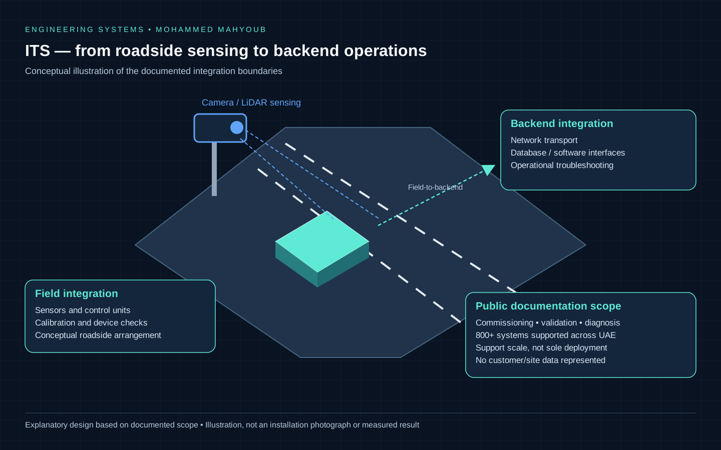
System overview
- Author
- Mohammed Mahyoub
- Scale
- 800+ intelligent transportation and traffic enforcement systems supported across the UAE.
- International service
- VITRONIC service assignments in the UAE (including Abu Dhabi and Dubai), Saudi Arabia, Oman, Rwanda, Erbil in Iraq, and Kenya.
- Role
- Field and systems engineering across cameras, LiDAR, sensors, control units, networking, databases, and software interfaces.
- Method
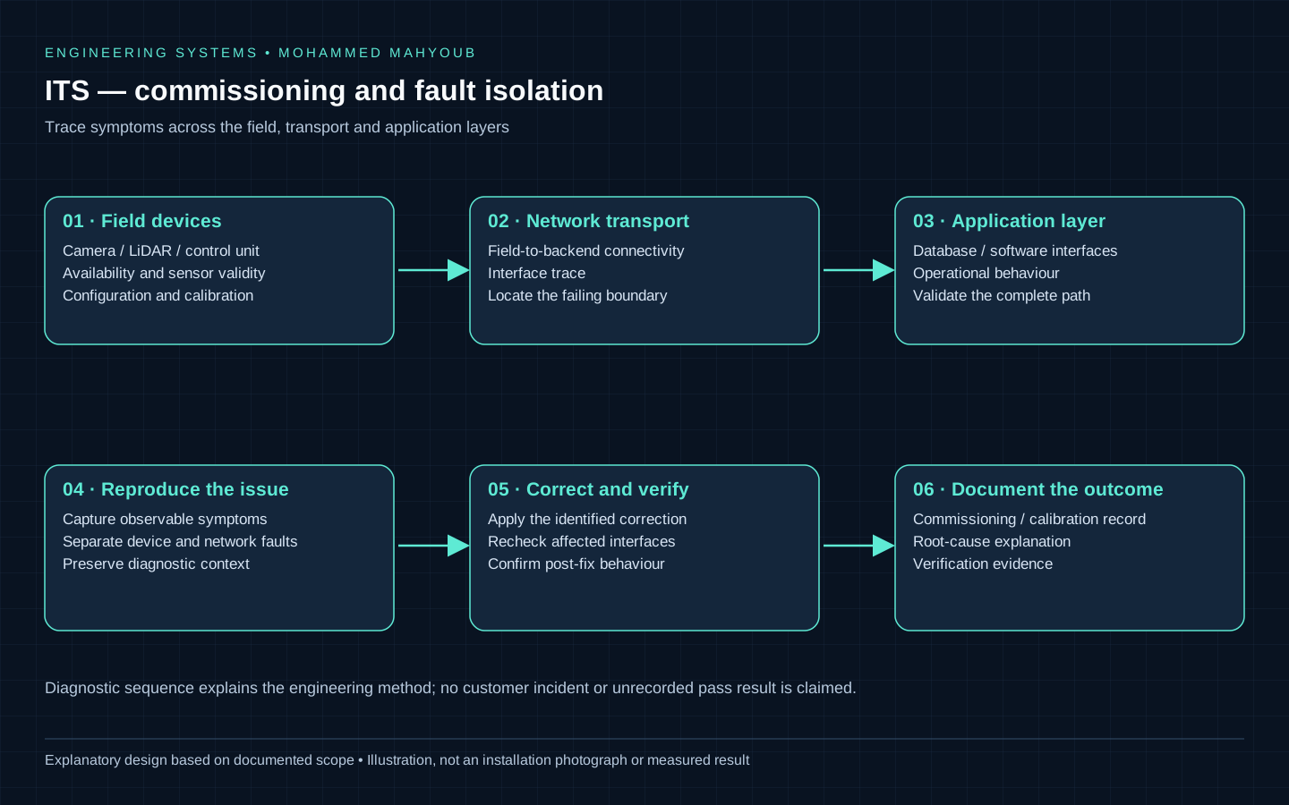
- Structured commissioning and root-cause analysis to resolve integration issues across hardware, networking and software.
Tracing an enforcement event across system boundaries
The documented responsibility spans roadside cameras, LiDAR, sensors and control units, transport connectivity, databases and software interfaces. The support scope covers systems across the UAE; no independently verified fleet count is stated. This case study focuses on integration and diagnosis, with customer and enforcement records excluded from the public material.
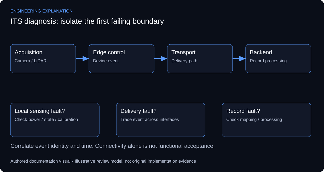
An event must remain traceable as it crosses the acquisition, edge-processing, transport and backend boundaries. A useful diagnostic record associates the device identity, event time, observed symptom and receiving service. These are an explanatory record model, not a disclosure of the deployed database schema or a claim that the system implements syslog. RFC 5424 supplies a reference for separating structured event content from its transport.
Diagnosis starts at the first boundary where expected behaviour differs from observed behaviour. A powered device can still have a sensing or calibration fault; an available IP endpoint can still have an application-interface fault. Checking the next boundary only after establishing the previous one avoids mistaking connectivity for complete functional acceptance.
For an anonymised review, capture a symptom, the boundary inspected, the evidence inspected, the corrective action and the follow-up observation. Calibration readings and acceptance thresholds must come from the applicable device procedure. The diagram below explains fault localisation without exposing customer addresses, enforcement images or installation-specific settings.
Review scenarios and expected evidence
These scenarios specify what evidence would support a review. They do not report additional completed tests.
| Review area | Method | Evidence to inspect |
|---|---|---|
| No event at edge | Inspect power, sensing state and local diagnostics | A local event or a documented device fault |
| Event at edge, absent at backend | Trace link, queue and receiving interface | Correlated event across the affected boundary |
| Event received, incomplete record | Review field mapping and processing errors | Expected record fields and explicit rejected-event handling |
| After corrective action | Repeat the affected functional path | Dated follow-up observation, not only a successful ping |
Technical references and provenance
Primary references support the engineering explanation, not claims about this project's undocumented configuration or results.
No customer records, device configurations or new calibration results are published. The review scenarios below describe how to assess the documented responsibility; they are not additional completed test claims.
Engineering rationale
Integration boundaries
Cameras, LiDAR and control units form one part of the system; network transport, databases and software interfaces form the next. A fault should be traced across those boundaries rather than attributed to the first device showing a symptom.
Commissioning and diagnosis
The documented work covers installation support, commissioning, calibration, validation and operational troubleshooting. Evidence should distinguish device health, transport availability and application behaviour. This public case study omits customer identities, site configurations and enforcement data.
What the scale means
The case study describes operational support and integration responsibilities across UAE deployments; it does not attribute all system design or deployment to one engineer.
Evidence and validation
Review the documented implementation against these validation topics; measured results are shown only where provided by the source.
- Device availability and sensor validity
- Field-to-backend interface trace
- Calibration/commissioning record
- Fault reproduction and post-fix verification
Visual documentation
These repository diagrams explain the documented implementation and integration boundaries. They are explanatory documentation; physical-build photographs and raw operational results are not published here.