Robotics · RGB-D Mapping · Embedded Integration
Reconnaissance Robot — RGB-D Mapping & Remote Control
Designed, programmed, integrated and tested a reconnaissance rover combining Kinect-based 3D mapping, ultrasonic 2D mapping, environmental sensing, GPS/GSM reporting and remote control.
Implemented Project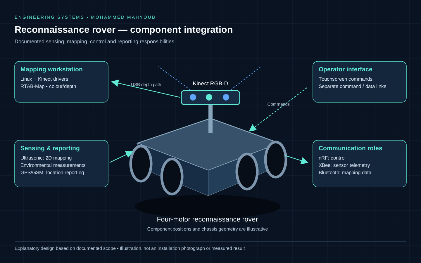
System overview
- Author
- Mohammed Mahyoub
- Role
- End-to-end implementation: system design, programming, assembly, integration, testing and documentation.
- Mapping
- Integrated a Microsoft Kinect RGB-D sensor with RTAB-Map on Linux; built the required software and sensor drivers. Used ultrasonic sensing for 2D mapping.
- Interfaces
- Integrated a four-motor rover, a touchscreen controller, XBee sensor telemetry, nRF control, Bluetooth mapping data and GPS/GSM location reporting.
- Integration
- Resolved software-build and Kinect-driver compatibility issues; retained a wired USB connection for Kinect depth data.
Separating mapping, command and telemetry paths
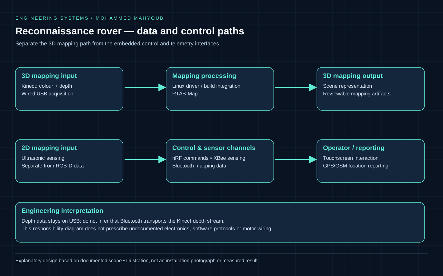
The rover combines four-motor motion, Kinect RGB-D acquisition, RTAB-Map on Linux, ultrasonic sensing, a touchscreen controller and several communication channels. Its documented integration issue was software-build and Kinect-driver compatibility. The wired USB depth-data path was retained; it should not be redrawn as a wireless video feed.
RGB and depth observations need a consistent sensor configuration before mapping is interpreted. RTAB-Map provides graph-based mapping and loop-closure functionality, but citing its capabilities does not establish which parameters were enabled on this rover. The public source documents the RGB-D integration, not a recovered launch file, a measured map accuracy or a demonstrated loop-closure benchmark.
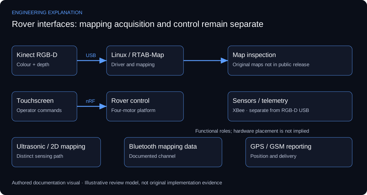
The touchscreen and nRF command path, XBee sensor telemetry, Bluetooth mapping data and GPS/GSM reporting have distinct roles. Mapping acquisition failure therefore cannot be diagnosed from the control channel alone. A reference integration review isolates each interface, then checks how observations and commands are associated with the correct source and time.
A useful mapping demonstration would pair the input sensor view with the produced map and acquisition conditions. Original build photographs, captured point clouds and operating logs are not in the available public release. The existing rover illustration and the interface review below explain the actual documented scope; neither is a substitute for those records.
Review scenarios and expected evidence
These scenarios specify what evidence would support a review. They do not report additional completed tests.
| Review area | Method | Evidence to inspect |
|---|---|---|
| RGB-D acquisition | Confirm colour/depth availability and calibration context | Paired sensor capture and configuration |
| Remote control | Exercise command reception separately from mapping | Command/action record; no invented response time |
| Sensor telemetry | Trace the stated XBee and sensor path | Source identity and sample sequence |
| GPS/GSM reporting | Distinguish position acquisition from message delivery | Position status and delivery record |
Technical references and provenance
Primary references support the engineering explanation, not claims about this project's undocumented configuration or results.
No physical-build photograph or measured point-cloud result has been reconstructed from a generated illustration.
Engineering rationale
Two mapping paths
Kinect supplies colour and depth to RTAB-Map on Linux for 3D mapping. Ultrasonic sensing supplies a separate 2D mapping path. These are complementary interfaces; Bluetooth mapping data is not described as carrying the Kinect depth stream.
Control and reporting interfaces
The four-motor rover and touchscreen controller are integrated with nRF control, XBee sensor telemetry, Bluetooth mapping data and GPS/GSM location reporting. Separate channels make it necessary to document which data uses which link.
The integration constraint
Software builds and Kinect drivers required compatibility work. The retained wired USB connection is a documented engineering decision for the depth-data path. The new diagram is a functional overview rather than a circuit schematic or a claim about undocumented motor-driver wiring.
Evidence and extension
The public description records design, programming, assembly, integration and testing. Source code, raw maps and physical-build photographs are not present in the inspected repository. The acceptance checklist below is a suggested way to document those artifacts when available.
Evidence and validation
Review the documented implementation against these validation topics; measured results are shown only where provided by the source.
- Driver compatibility and USB depth acquisition
- RTAB-Map output with scene context
- Command and telemetry channel mapping
- Motor/sensor response and location reporting
Visual documentation
These repository diagrams explain the documented implementation and integration boundaries. They are explanatory documentation; physical-build photographs and raw operational results are not published here.